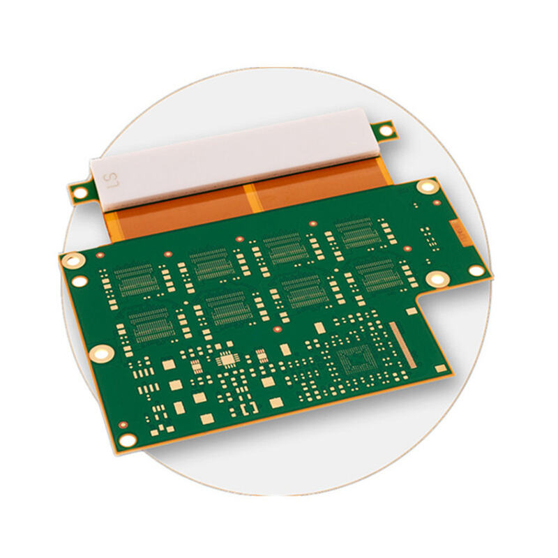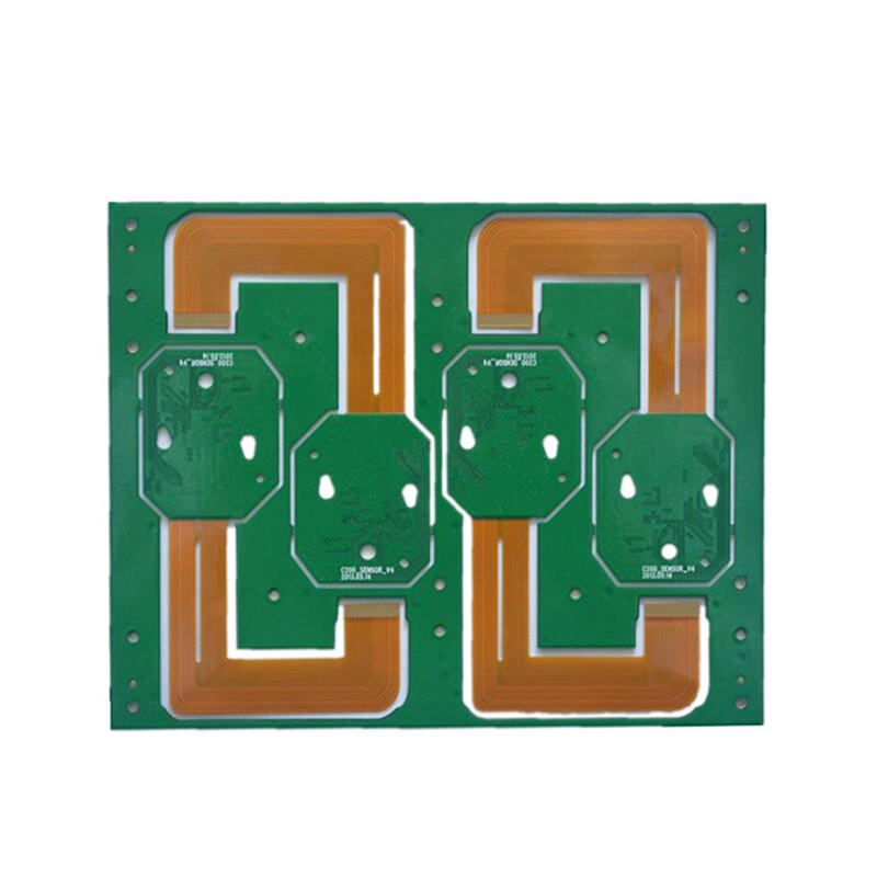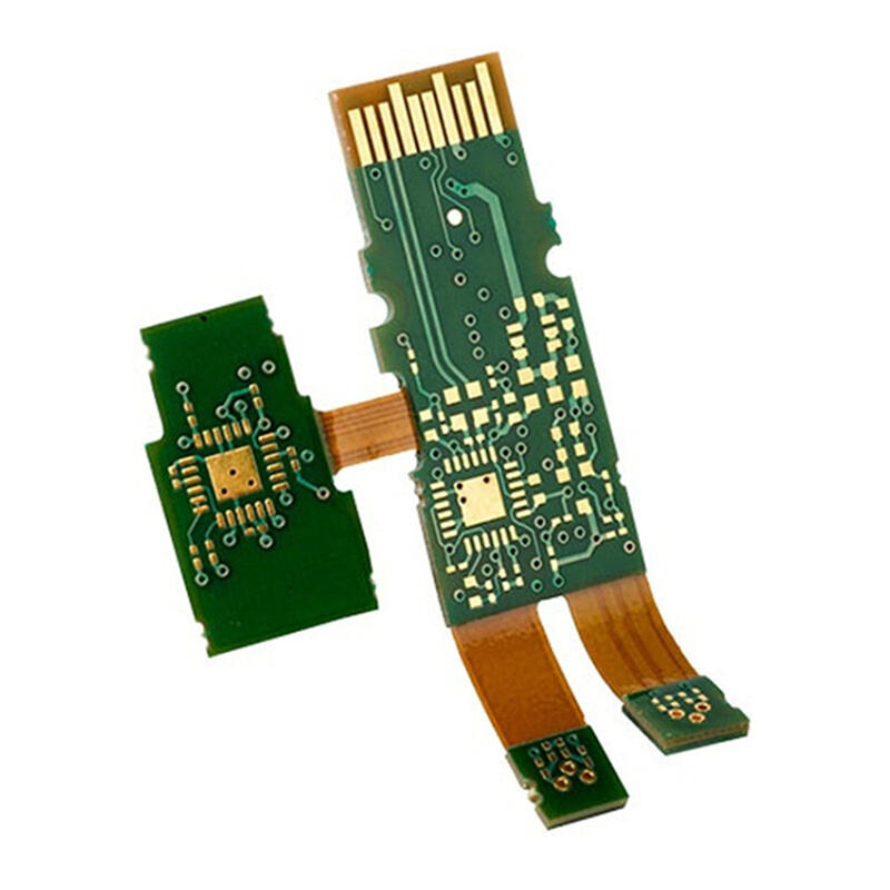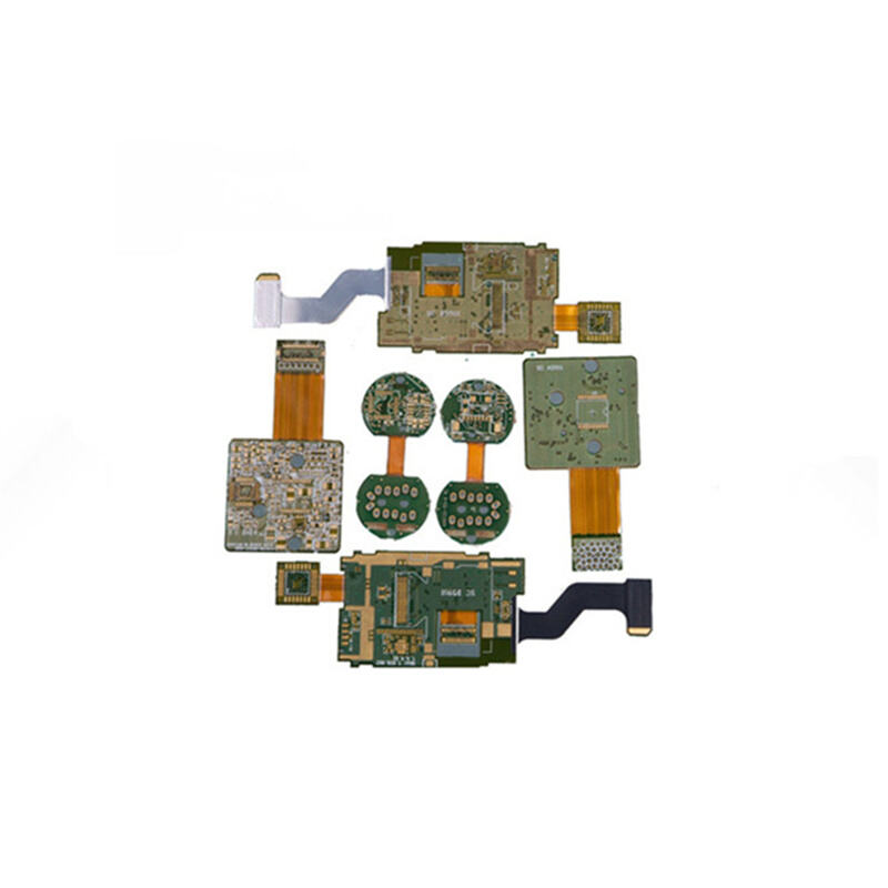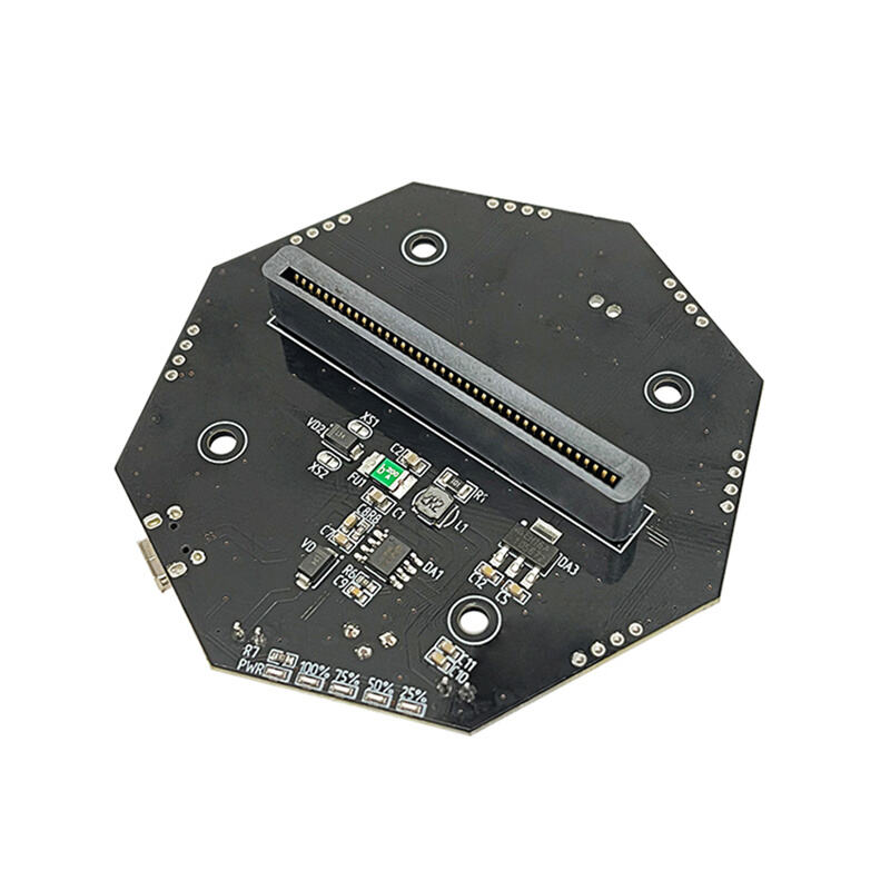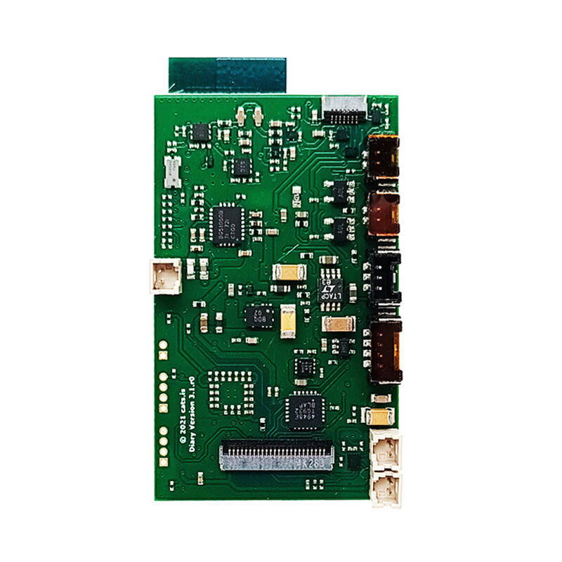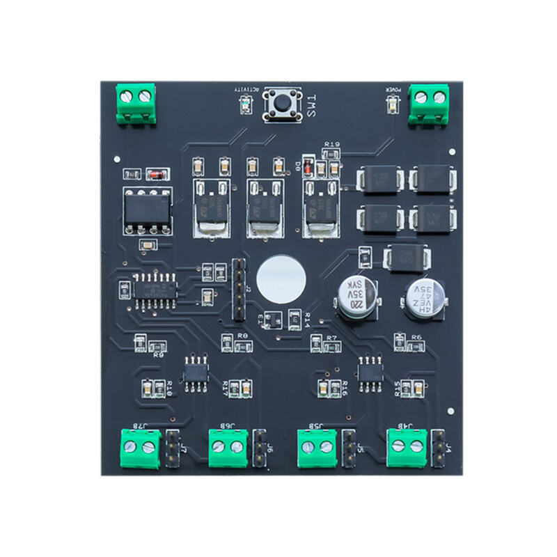
This custom rigid-flex printed circuit board (Rigid-Flex PCB) combines the structural stability of rigid PCBs with the flexibility of FPCs, designed to meet the demands of complex, space-constrained electronic devices. It integrates rigid sections (for component mounting and structural support) and flexible polyimide (PI) sections (for dynamic interconnection and bending), enabling 3D wiring and multi-module integration that traditional rigid PCBs cannot achieve.
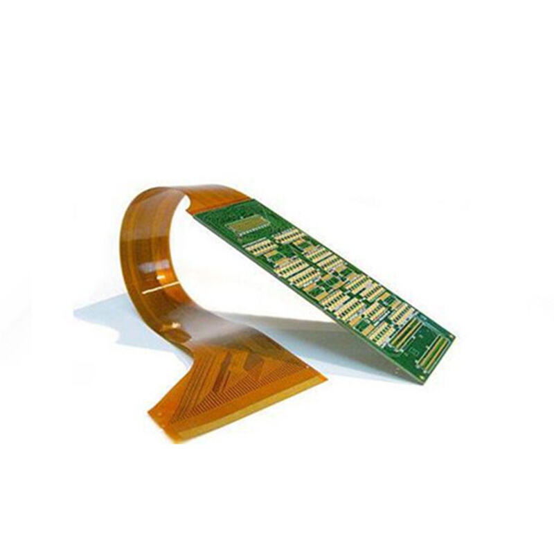
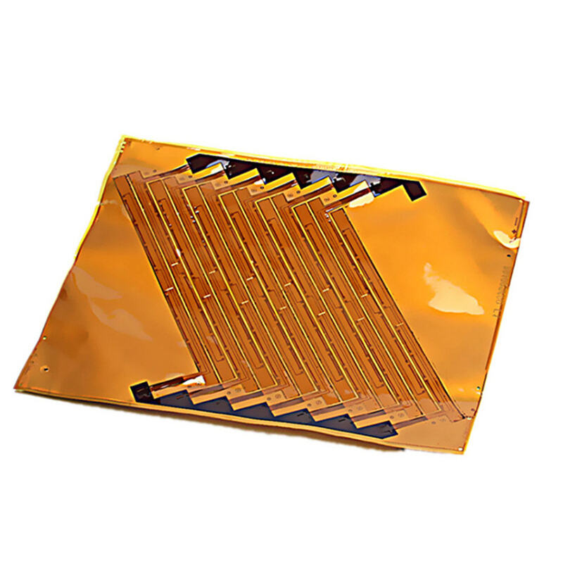
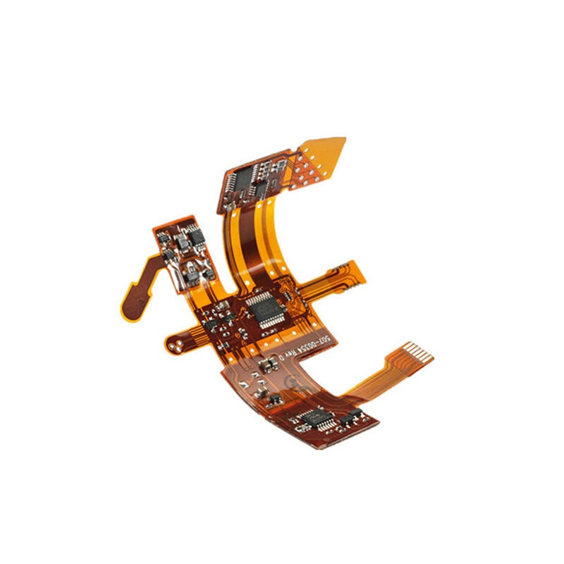
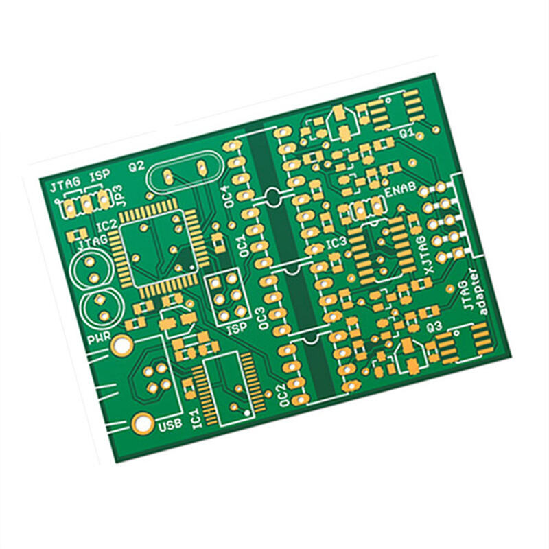
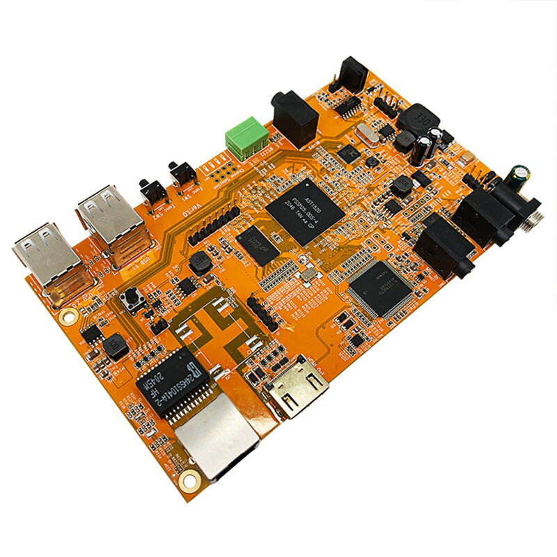
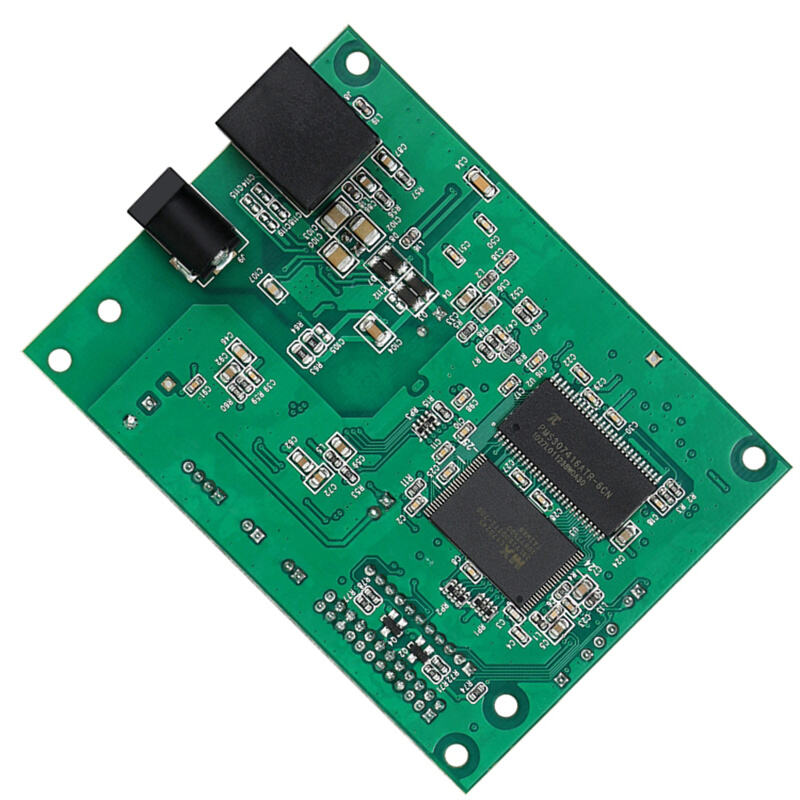
Constructed with high-performance FR-4 rigid substrates and flexible PI materials, this Rigid-Flex PCB features precision-etched copper circuits and dedicated SMT component pads (for ICs, connectors, and passive components), supporting reliable component assembly and stable signal transmission. The flexible sections allow repeated bending and folding, making it ideal for devices requiring dynamic movement or compact internal layouts, while the rigid sections provide robust support for high-density component mounting.
Our advanced manufacturing process ensures excellent thermal stability, mechanical durability, and electrical performance, with resistance to temperature fluctuations, vibration, and repeated bending stress. We offer full customization services, including layer count configuration, rigid-flex ratio adjustment, component pad layout, and impedance control, to match your specific product requirements. Whether for consumer electronics, medical devices, automotive electronics, or industrial equipment, this Rigid-Flex PCB provides a highly integrated, space-efficient, and reliable interconnection solution that simplifies device design and accelerates time-to-market.
| Place of Origin | China |
| Brand Name | [Your Brand] |
| Model Number | Rigid-Flex-PCB-005 |
| Certification | RoHS, REACH, ISO 9001, IPC-6012 |
| Rigid Base Material | FR-4 (TG130/TG150 customizable) |
| Flexible Base Material | Polyimide (PI) |
| Conductor Material | Electrodeposited Copper |
| Layer Count | 4–12 layers (customizable) |
| Minimum Line Width | 0.075mm |
| Minimum Line Spacing | 0.075mm |
| Board Thickness | 0.4mm–2.0mm (customizable) |
| Component Pads | SMT pads for ICs, connectors, resistors, capacitors |
| Connector Type | Gold-plated edge connector / FPC connector (optional) |
| Operating Temperature | -40°C to +125°C |
| Bending Life | ≥5,000 times (depending on bend radius) |
· Consumer Electronics: Used in smartphones, tablets, and wearable devices for 3D module interconnection and compact design.
· Medical Devices: Integrated into portable diagnostic tools and implantable devices for reliable performance in miniaturized layouts.
· Automotive Electronics: Applied in in-vehicle infotainment systems and sensor modules to withstand vibration and temperature changes.
· Industrial & IoT: Utilized in industrial sensors and smart meters for flexible, high-density circuit integration.
1. Rigid-Flex Integration: Combines rigid PCB stability and FPC flexibility, enabling 3D wiring and space optimization.
2. High Component Density: Rigid sections support high-density SMT component mounting, improving device integration.
3. Mechanical Durability: Flexible sections withstand repeated bending, while rigid sections provide robust structural support.
4. Signal Integrity: Precision trace layout ensures stable high-speed signal transmission in complex layouts.
5. Full Customization: Tailored to your rigid-flex ratio, layer count, component layout, and electrical specifications.
Q: What is the difference between this Rigid-Flex PCB and a standard FPC?
A: Unlike pure FPCs, this Rigid-Flex PCB includes rigid FR-4 sections for component mounting and structural support, while flexible sections enable dynamic interconnection, making it ideal for high-density, 3D device designs.
Q: Can I customize the ratio of rigid to flexible sections?
A: Yes, we fully support custom rigid-flex ratios and shape design to match your device’s mechanical and electrical requirements.
Q: What is the lead time for custom Rigid-Flex PCB samples?
A: Sample lead time is typically 7–10 working days, while mass production lead time is 10–20 working days, depending on design complexity and order quantity.
Q: Is this Rigid-Flex PCB compatible with lead-free soldering processes?
A: Yes, all our Rigid-Flex PCBs are RoHS-compliant and fully compatible with lead-free reflow soldering processes.
Professional PCBA manufacturer in China, providing one-stop manufacturing services with excellent quality and service.
Room 602 & 603, Building C, Qianwan Key & Core Technology Industrial Park, Bao'an District, Shenzhen, China
Copyright © Shenzhen UC Industrial Limited All Rights Reserved Privacy Policy